
In the world of construction, precision is paramount. One misstep in a drawing can lead to costly errors and delays. That’s where mechanical drawing comes into play. It is the unsung hero of construction projects, offering the detailed information needed to bring designs to life. Whether you’re overseeing a skyscraper or a modest home renovation, understanding mechanical drawing can make or break your project’s success.
This blog post will guide you through the essentials of mechanical drawing, offering insights into various techniques and tools that can enhance your construction projects. From understanding the types of technical drawings to adopting advanced drawing techniques, we aim to provide a comprehensive overview for construction clients eager to make informed decisions.
What is Mechanical Drawing?
Mechanical drawing is a detailed art form that involves creating drawings of machines, mechanisms, and structures. It is a fundamental skill in engineering, architecture, and design, communicating complex ideas in a visual form. This technical drawing serves as a blueprint, visually representing how something functions or is constructed, ensuring that all the items come together seamlessly.
This type of drawing is not limited to a single industry. It is crucial in various sectors, including construction, where precision and accuracy are vital. Whether you’re constructing buildings or assembling component parts, mechanical drawing provides the design intent and detailed drawings needed to bring projects to life.
Types of Technical Drawings
Architectural Drawings
Architectural drawings are the foundation of any construction project. They offer precise depictions of every aspect of the proposed construction, from the layout to the materials used. These drawings ensure that the design intent is clear, allowing all stakeholders to understand the project’s scope.
Mechanical Engineering Drawings
These drawings define the requirements for engineering products and components. They illustrate how different parts will be assembled, providing a clear roadmap for construction teams. By using mechanical engineering drawings, construction projects can avoid costly errors and maintain design accuracy.
Electrical Drawings
Electrical drawings depict and notate designs for electrical systems. They provide detailed information about the layout and connections of electrical components, ensuring that all elements work harmoniously. These drawings are essential for safety and functionality in construction projects.
Structural Drawings
Structural drawings depict the various components, connections, and dimensions of a project. They clearly communicate the structural framework necessary for any building or infrastructure project, ensuring that stability and safety are prioritized.
Civil/Site Drawings
Civil or site drawings depict the layout and design of a construction site. They provide an overview of the project’s scope, ensuring that all elements align with the design intent. These drawings help streamline the construction process and prevent costly delays.
Essential Elements of Mechanical Drawings
Lines
In engineering drawings, lines are the building blocks. There are three main types of lines used—center lines, hidden lines, and extension lines. Center lines indicate symmetry, hidden lines show concealed components, and extension lines extend a line on the object to the dimension line, ensuring an accurate depiction of an object’s form.
Symbols
Symbols in mechanical drawings represent different features of objects within the drawing. They ensure that complex ideas are communicated effectively, allowing for a universal understanding of various components and their functions.
Materials Block
The materials block contains information about the materials used in the project. It ensures that all parties involved know exactly what materials are needed, preventing costly substitutions or errors during construction.
Revision Block
Located in the upper right-hand corner of the drawing, the revision block shows details about any changes made to the drawing. It ensures that the most up-to-date information is always available, reducing confusion and ensuring design accuracy.
Title Block
The title block, located at the bottom right-hand corner of the drawing, provides context for the drawing. It includes essential information such as the project name, date, and the drafter’s name, offering a clear reference for all parties involved.
Drawing Tools and Software for Mechanical Drawings
Manual Drafting Instruments
Before the advent of digital tools, manual drafting instruments like pencils, pens, and paper were the norm. These traditional tools still hold value, especially in situations where quick, freehand drawing is required. They allow for on-the-spot adjustments and encourage a tactile understanding of the drawing process.
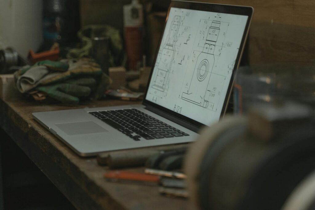
Computer-Aided Drafting or Design (CAD) Software
CAD software like Autodesk and AutoCAD has revolutionized the way mechanical drawings are created. These tools allow for precise, detailed drawings that can be easily modified and shared. They enable designers to create two-dimensional and three-dimensional models, providing a comprehensive view of a project.
Technical Drawing Software
Beyond CAD, there are various technical drawing software options available, including Autodesk’s suite of 2D and 3D CAD tools. These programs offer advanced features, such as parametric modeling and rendering, allowing for highly accurate and detailed drawings.

Orthographic and Isometric Drawing Techniques
Orthographic Drawing
Orthographic drawing offers a 2D view of an object from multiple angles. It provides a comprehensive look at an object, allowing for accurate measurements and ensuring that all dimensions are clearly communicated. This technique is essential for creating detailed, precise drawings that guide the construction process.
Isometric Drawing
Isometric drawing provides a 3D view of an object, with vertical lines drawn vertically and horizontal lines at 30 degrees to the horizontal. This technique allows for the visualization of all the object’s details and dimensions, offering a comprehensive view that aids in construction and assembly.
Isometric Drawings in Practice
Isometric drawings can be particularly useful in construction projects, as they offer a clear view of how different components fit together. By visualizing the object in three dimensions, construction teams can better understand the design intent and minimize errors during assembly.

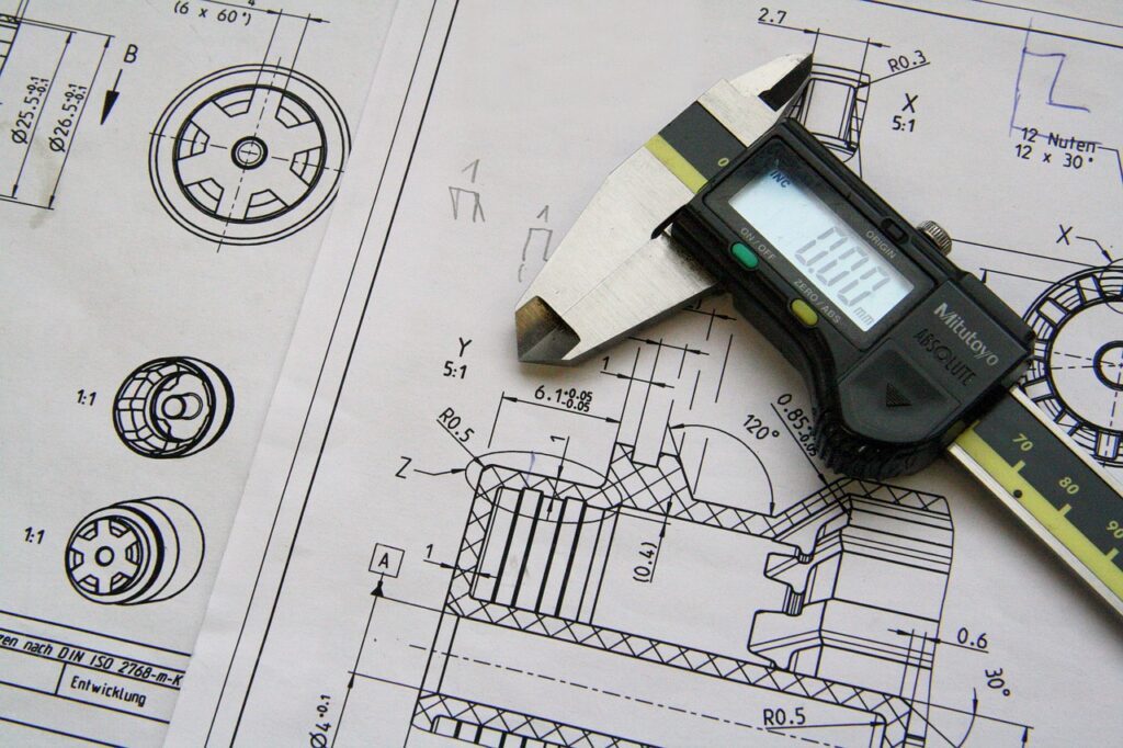
Dimensioning and Sectioning in Mechanical Drawings
Dimensioning
Dimensioning involves adding measurements to a drawing to provide a clear and complete description of an object. It ensures that all parties involved have a precise understanding of the object’s size and scale, reducing the risk of errors during construction.
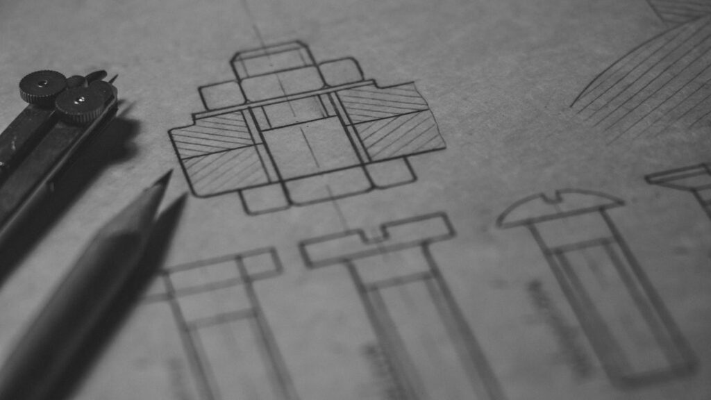
Sectioning
Sectioning involves cutting an object to show internal details. Sectional views can be used to reveal hidden components, ensuring that all elements are accurately represented and understood. This technique is vital for complex projects with intricate designs.
Sectional Views in Construction
Sectional views are particularly helpful in construction projects, as they offer a detailed look at how different parts of a structure fit together. By providing a clear view of interior details, sectional views help construction teams make informed decisions and avoid costly errors.

Creating Assembly and Detail Drawings
Assembly Drawings
Assembly drawings show the components of an object and how they are assembled. They provide a clear roadmap for construction teams, ensuring that all components fit together seamlessly. This type of drawing is crucial for projects with multiple parts, as it prevents errors and enhances design accuracy.
Detail Drawings
Detail drawings offer an in-depth look at individual components of an object. They provide the exact dimensions and specifications needed for each part, ensuring that all components are accurately constructed and assembled.
Isometric Views in Assembly Drawings
Isometric views can be used in assembly drawings to show the overall arrangement of an object’s components. By providing a 3D perspective, these views help construction teams better understand the design intent and minimize errors during assembly.
Reading and Interpreting Technical Drawings
Understanding Technical Drawing Conventions
Technical drawings follow specific conventions, such as ISO 128, which must be understood to accurately read and interpret them. These conventions ensure consistency and clarity, allowing for a universal understanding of the drawing’s content.
Recognizing Lines, Symbols, and Notations
Recognizing the different types of lines, symbols, and notation systems used in technical drawings is essential for accurate interpretation. By understanding these elements, construction clients can visualize the three-dimensional object from the two-dimensional drawing, ensuring design accuracy.
Visualizing Three-Dimensional Objects
Visualizing a three-dimensional object from a two-dimensional drawing is a crucial skill in construction. By accurately interpreting the drawing, clients can ensure that all components fit together seamlessly, avoiding costly errors and delays.
Best Practices for Mastering Mechanical Drawing
Creating Depth with Parallel Lines
Using parallel lines in drawings can create a sense of depth, enhancing the accuracy and clarity of the drawing. This technique is particularly useful in complex projects with multiple components, as it helps convey the design intent.
Extension and Hidden Lines
Extension lines are used to extend a line on the object to the dimension line, ensuring accurate measurements. Hidden lines show hidden components in a device, providing a complete view of the object’s structure.
Exact Dimensions for Clarity
Using exact dimensions is essential for providing a clear and complete description of an object. By specifying precise measurements, construction teams can ensure that all components fit together seamlessly, avoiding costly errors.
Applications of Mechanical Drawing in Engineering
Communication of Complex Ideas
Mechanical drawing is used to communicate complex ideas and designs across various fields, including engineering, architecture, and design. By providing detailed drawings, these disciplines can bring intricate projects to life with precision and accuracy.
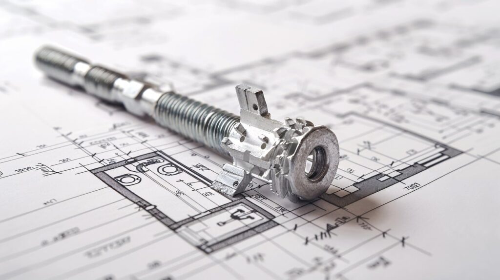
Detailed Drawings of Machines and Structures
Mechanical drawing is essential for creating detailed drawings of machines, mechanisms, and structures. By offering a visual representation of the design intent, these drawings ensure that all components fit together seamlessly, enhancing design accuracy.
Role in Construction Projects
In construction projects, mechanical drawing plays a vital role in ensuring that all elements align with the design intent. By providing detailed, accurate drawings, construction teams can minimize errors and enhance communication, leading to successful project completion.
The Role of Engineering Drawing in Mechanical Design
Essential for Industry Communication
Engineering drawings are essential for communicating ideas in industry and engineering. By providing detailed, accurate drawings, these documents ensure that all parties involved understand the design intent and requirements.
Visualization of Three-Dimensional Objects
Engineering drawings are used to visualize three-dimensional objects from two-dimensional drawings. This skill is crucial for construction teams, as it allows them to accurately interpret the design intent and minimize errors during assembly.
Detailed Drawings for Design Accuracy
Engineering drawings provide the detailed, accurate drawings needed to bring complex designs to life. By ensuring that all elements align with the design intent, these drawings enhance communication and design accuracy.
Technical Drawing Software for Mechanical Drawings
Autodesk Technical Drawing Software
Autodesk offers a suite of technical drawing software, including 2D and 3D CAD tools. These programs provide advanced features that allow for highly accurate and detailed drawings, enhancing construction project success.
AutoCAD for Technical Drawings
AutoCAD is a popular CAD software used for creating technical drawings. Its advanced features and user-friendly interface make it an excellent choice for construction clients seeking precision and accuracy in their drawings.
Autodesk Revit for BIM Projects
Autodesk Revit is a popular BIM software used for creating detailed drawings of buildings and infrastructure projects. Its advanced features allow for highly accurate and detailed drawings, ensuring design accuracy and project success.
Advanced Mechanical Drawing Techniques
Parametric Modeling for 3D Models
Parametric modeling allows for the creation of 3D models from 2D technical drawings. This technique enhances design accuracy and allows for easy modifications, ensuring that all elements align with the design intent.
Rendering and Visualization for Accuracy
Rendering and visualization techniques create highly accurate still images and animations from computer models and technical drawings. These techniques provide a comprehensive view of the design intent, enhancing communication and accuracy.
Layer Management for Object Organization
Layer management techniques allow for the organization of all objects in a drawing, ensuring clarity and accuracy. By managing layers effectively, construction teams can ensure that all elements align with the design intent, minimizing errors and enhancing communication.

Mastering Mechanical Drawing for Construction Success
Mastering mechanical drawing requires practice and patience. It is essential to understand the conventions used in technical drawing, such as ISO 128, to ensure accuracy and clarity. Recognizing the different types of lines, symbols, and notation systems used in technical drawings is crucial for accurate interpretation.
By adopting best practices and utilizing advanced techniques, construction clients can enhance their mechanical drawing skills and ensure project success. Whether you’re overseeing a skyscraper or a modest home renovation, mastering mechanical drawing provides the detailed information needed to bring your vision to life.
For those eager to explore more, consider reaching out to BB&A Construction Services for expert guidance and support. With a focus on quality and precision, our team is dedicated to helping clients achieve their construction goals with confidence and accuracy.
Resources for Mechanical Drawing
Recommended Books
-
Technical Drawing with Engineering Graphics by Frederick E. Giesecke — A comprehensive guide that covers fundamentals and advanced concepts in technical drawing.
-
Engineering Drawing and Design by David Madsen — Offers insights into creating precise engineering drawings with a focus on design techniques.
-
Blueprint Reading for Builders by Sam Kubba — A practical resource for understanding and applying blueprint reading skills in construction projects.
Professional Associations
-
American Design Drafting Association (ADDA) — Provides certification, networking opportunities, and resources for drafting professionals.
-
American Society of Mechanical Engineers (ASME) — Offers resources, workshops, and standards for mechanical engineering professionals.
-
National Institute for Certification in Engineering Technologies (NICET) — Provides certification credentials and resources for engineering technicians.
Industry Blogs and Forums
-
Engineering.com Blog — Features articles on the latest trends and innovations in engineering.
-
GrabCAD Community — A platform for engineers to share CAD models and collaborate on projects.